
Teflon ‘PTFE’ Face Seal Shrink Fit FEA Analysis
FEA, known as Finite Element Analysis, is a valuable tool used by many Engineers in the product development and design process. It can reduce product development lifecycle time by allowing for shorter and more frequent design validation iterations. In this article, I discuss how CADify utilized FEA to design a Teflon face seal used in a commercial flush valve.
Before we jump into the analysis, it is important to understand the environmental conditions so that we can determine our boundary conditions for the finite element model. Max average steady-state fluid pressure, i.e. the average water pressure coming into most commercial flush valves from the city in the United States, is around 150psi. Interestingly though, the transient response coming into the valve body can reach 300psi under certain “impulse” conditions. As a conservative design approach, we utilized the 300psi transient impulse pressure as a precursor to defining our minimum gasket sealing pressure in our FEA stress analysis. This way, we ensure that the Teflon gasket does not leak, even under a 300psi transient fluid pressure condition.
Let’s get started with the shrink fit stress analysis!
Tailpipe Assembly


Finite Element Model - Geometry
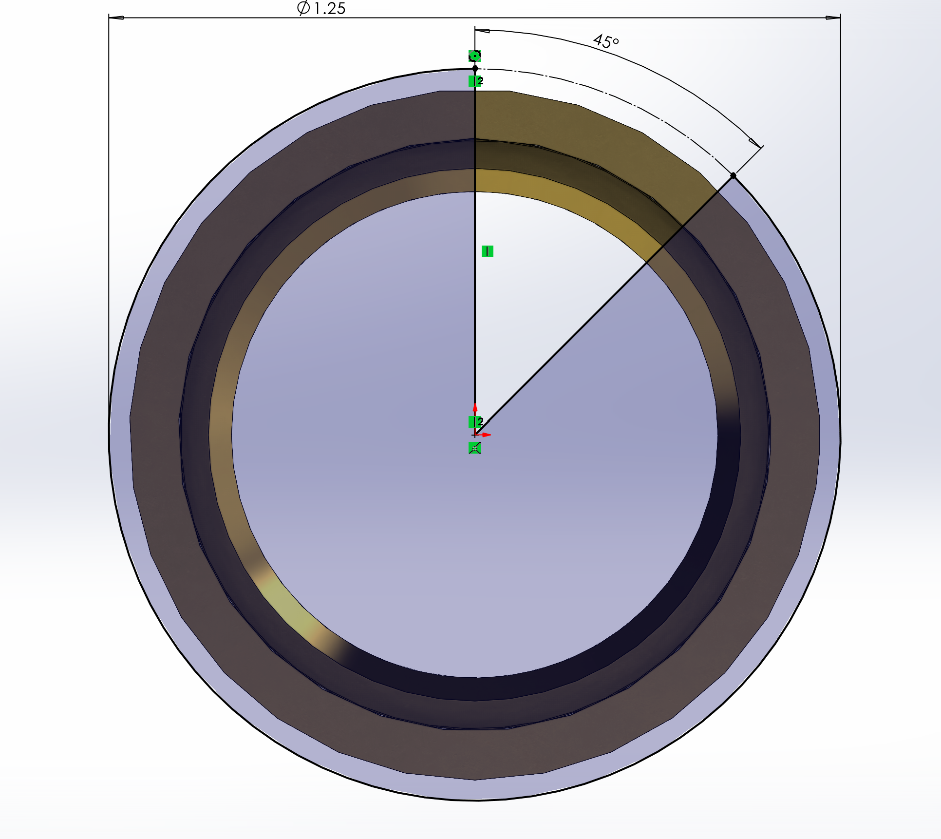
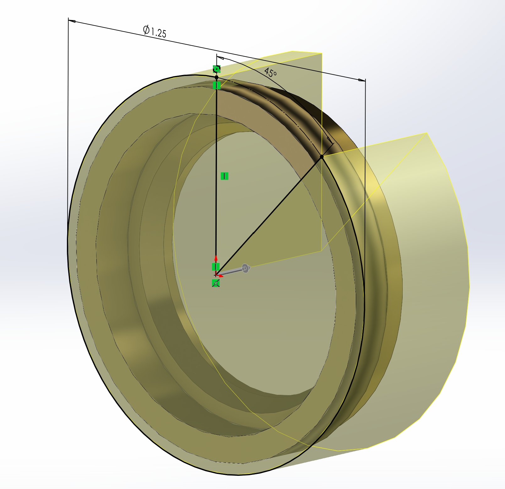
Engineers often downplay the importance of optimizing geometry when setting up an FEA model. A well optimized finite element model could save hours or even days of computation time! In our case, we cut the model and utilized the cyclical 1/8th symmetry to reduce simulation time exponentially.
As seen above, the full Tailpipe assembly consists of many components. For our shrink fit analysis however, we only at the looked at the interaction between the Face Seal, Tailpipe, and Bushing.
View the gallery below to see the process we took to simplify the geometry for our finite element model.


Finite Element Model - Study Properties & Part Configuration
For our study properties in Solidworks Simulation Professional, we left our solver type as automatic. This tells Solidworks to automatically select the best solver to reduce solve time.
To further reduce the solve time we selected the brass components and made them fixed and rigid. I know what you are thinking… this can’t possibly be accurate… Well, you are correct. This isn’t accurate, and will produce greater stresses on our Teflon Face Seal since it is now pressed between two rigid and fixed bodies. My argument is that we have now produced a slightly more conservative finite element model and simultaneously reduced the solve time since the solver doesn’t have to iterate for the material response of the brass components. We are only able to do this because we know that the stiffness of Teflon is much less than the stiffness of brass. Additionally, the purpose of our analysis is to obtain the sealing pressure and ensure that the Teflon Face Seal will not fail, so making the brass components rigid and fixed will only aid in our goal.


Finite Element Model - Local Component Connections & Fixtures
Connections and fixtures can make or break the finite element model. It is important to constantly review both boundary condition types prior to running your simulation.
We added two types of local component interactions to our FEA model: friction based contact and shrink fit. The contact set takes place between the Teflon Face Seal and the Bushing, while the shrink fit set takes place at the 0.025mm interference between the Teflon Face Seal and the Tailpipe. Remember how we made the brass components rigid and fixed? Well that decision, coupled with our contact and shrink fit interactions, will reduce simulation time and provide conservative simulation results.
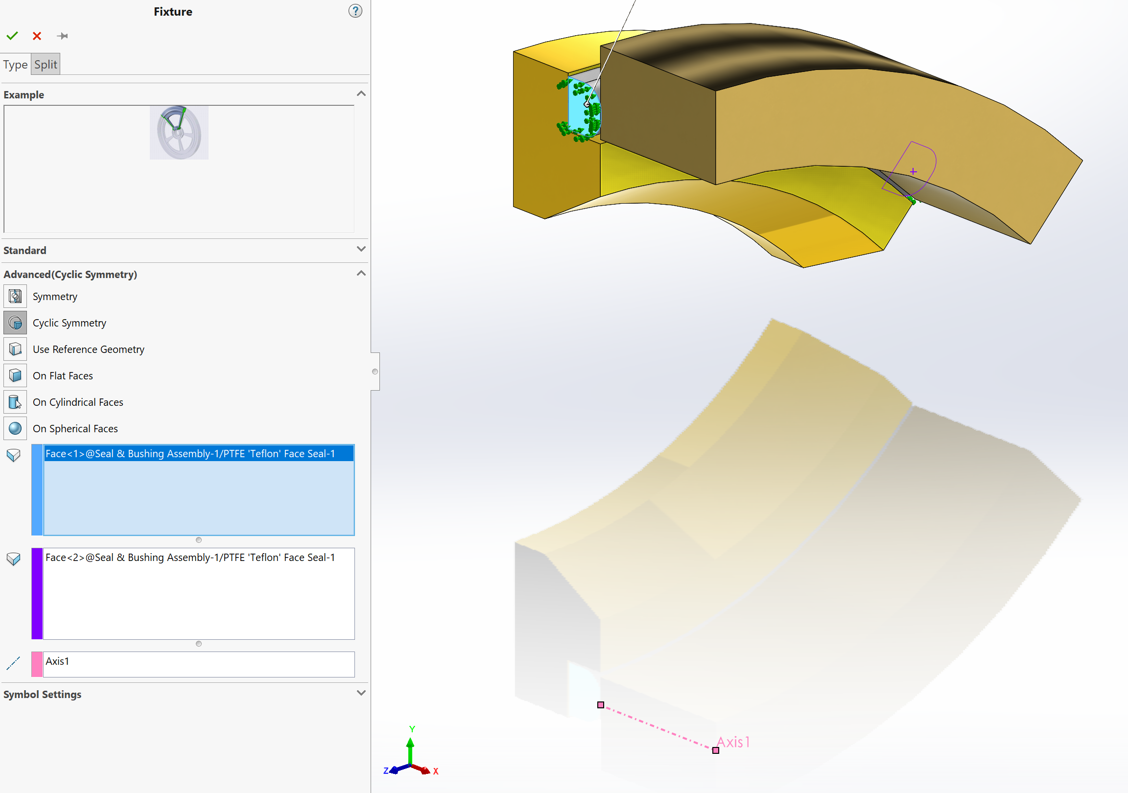
Probably the greatest impact to reducing our solve time will be the implementation and utilization of the cyclic symmetry fixture. Remember that 1/8th pie cut we made to the model previously? That extrude cut is the precursor to setting up our cyclic symmetry fixture. By defining an axis and selecting the symmetry faces, Solidworks will try to establish a stiffness matrix with moment/force couples at the fringes of the symmetry surface planes. Please note to exclude the fringes of the model from the results as there may be unrealistic divergence due to the cyclic symmetry fixture. To counter this, I like to only probe results between the two cyclic surfaces.
View the images below to follow our process.


Finite Element Model - Mesh
Meshing is an important element, no pun intended, to setting up any FEA model. Mesh element density directly impacts the solver type and simulation time exponentially.
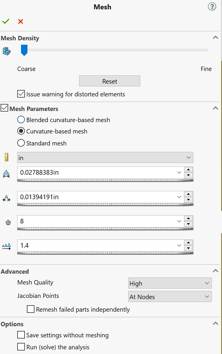
For our model, we used part based mesh controls to determine mesh sizing. We set the rigid and fixed brass components to course and the Teflon Face Seal to fine in Solidworks. The options that directly drive element sizing is selected in the master mesh settings. From here, we can define Jacobian mesh quality, growth factor, and base element sizing. Further meshing diagnostics could be done to view Jacobian ratios, etc.. but that is out of the scope for this article. Our decision to make the mesh course for the brass components wasn’t just due to their fixed and rigid conditions. I find that in these contact and shrink fit conditions, having the target’s (i.e. the focus of your analysis) connection set part mesh density larger than the secondary set mesh density will cause less mesh and simulation solver errors.
The images below demonstrate the meshing steps we took.


Finite Element Analysis - Running the Analysis & Results
After meshing the model, we then ran the solver. In my experience, we can run into the majority of our issues here: under-constraint bodies, excessive displacements, and many other errors that will halt the simulation. Thankfully, we didn’t run into any issues and our simulation took 20 minutes to solve on my system. If we hadn’t simplified the model with cuts, symmetry fixtures, and rigid & fixed components, we would be looking at a simulation time in hours. Not minutes. This will allow us to iterate designs while keeping solver time to a minimum.
We can see from the results that our factor of safety was below 1.0, with a reaction force of 5.85lbs over a 0.0084in^2 surface area. This gives us a surface contact pressure of 700psi, which is larger than the environmental transient impulse fluid pressure of 300psi. Now we have a better understanding of how the material will respond. To iterate, we just simply reduced the shrink fit interface distance until our design produced a FS > 1 and a sealing pressure of over 300psi. This design optimization can be automated by setting up a design study and linking the variable(s) that influence the Tailpipe to Teflon Face Seal interference.
Thank you for following along! If you have any questions about the analysis or could use these types of services for your project(s), please book a free 30 minute consultation with me by following the link below.


Here is a Bonus Animation Video of the Material Response
About CADify
CADify LLC was founded to provide customer-centric design services to our clients. We take pride in the services we offer and aim for developing a synergistic relationship with our clients. We strive to build long lasting relationships with individuals and companies alike.