A Deep Dive into Thermal and Mechanical Stresses: CADify’s FEA Study on a Heavy Machinery Exhaust Pipe
Examining the performance of heavy machinery components under operational conditions is paramount for ensuring both efficiency and safety. A component of significant importance in this sphere is the exhaust pipe, whose functionality can profoundly influence the overall performance of the machinery. In this rigorous study orchestrated by CADify, we delved into a comprehensive Finite Element Analysis (FEA) to unravel the intricacies of thermal and mechanical stresses that a heavy machinery exhaust pipe navigates through during its operational phase. This analysis is meticulously crafted to furnish insights into the stress dynamics of the exhaust pipe, thereby exhibiting our adeptness in leveraging advanced simulation tools to distill actionable insights.
The spotlight of this analysis is on the transient and nonlinear aspects, which sets it a notch higher than conventional steady state and linear static analyses. Unlike a steady state analysis, which only explores the system's behavior at equilibrium, a transient analysis ventures into how the system reacts over time under varying conditions. This is pivotal in understanding the thermal behavior of the exhaust pipe assembly as it transitions through different operational phases, thus providing a more realistic depiction of its performance under actual working conditions.
Similarly, diverging from the linear static analysis, which operates under the assumption that material properties and structural behaviors remain linear, the nonlinear analysis delves into the realm where material properties, geometry, and boundary conditions evolve with the applied loads. In this study, the nonlinear analysis was further enhanced by employing a plasticity model for the 316 stainless steel material, capturing the nonlinear behavior of the material under high-temperature and high-stress conditions. This nonlinear approach unveils the exhaustive details of how the exhaust pipe responds to complex mechanical loads, especially when combined with the transient thermal loads.
By embarking on a nonlinear dynamic and transient thermal analysis, we transcend the simplistic assumptions of linearity and steadiness, venturing into a more realistic and complex analysis landscape. This advanced FEA approach, showcased in this study, underscores CADify’s commitment to delivering a deeper understanding and more accurate insights into the mechanical and thermal behaviors of critical machinery components. Through this lens, we extend a robust platform of technical expertise, demonstrating our prowess in navigating the complex waters of advanced FEA to drive actionable, real-world solutions.
Building the Assembly
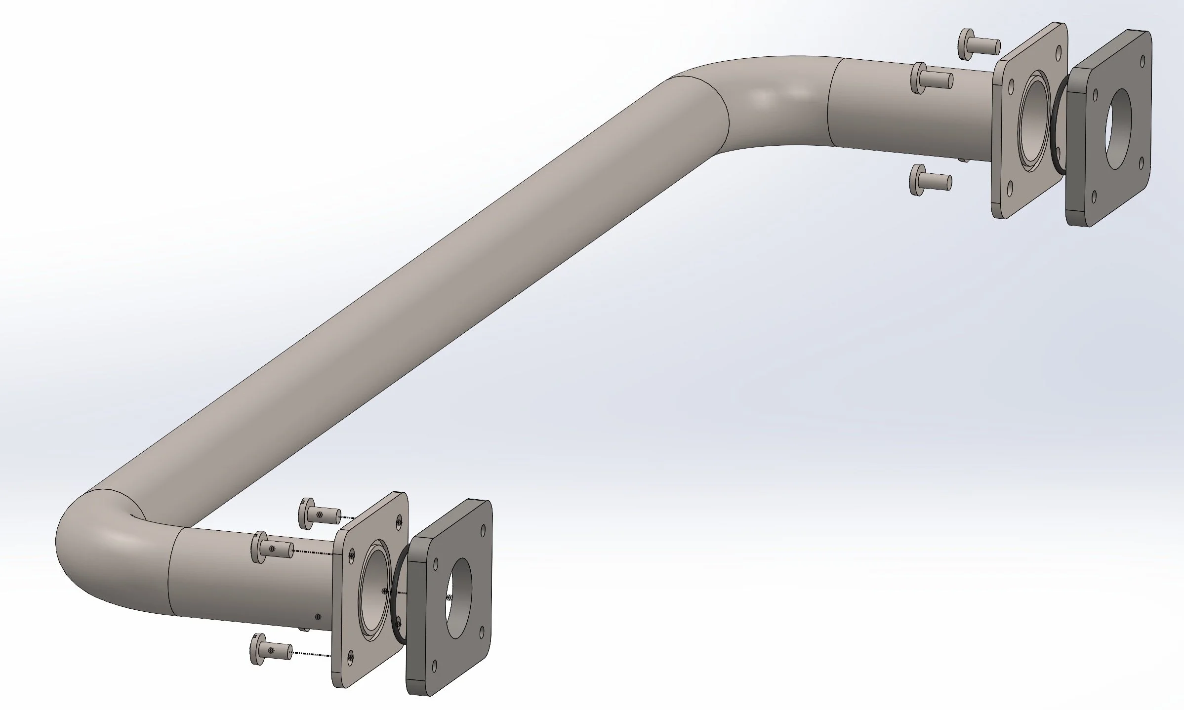
The process of analyzing the heavy machinery exhaust pipe assembly initiated with the careful construction of a detailed model of the assembly. The first image, an exploded view, breaks down the assembly to display each component and its spatial relationship to others, providing a clear understanding of the assembly's structure. Conversely, the second image, an angled view, offers a consolidated perspective, demonstrating how these components integrate to form the complete assembly. These visuals serve as a foundational blueprint guiding the subsequent steps of our analysis.
Creating an accurate model is crucial as it forms the base upon which the entire analysis rests. A well-constructed model ensures that every aspect of the assembly is captured and ready for simulation. The model was created in SolidWorks, a leading Computer-Aided Design (CAD) software, ensuring precision and accuracy in representation. This approach towards modeling ensures a comprehensive foundation, setting the stage for the thorough analysis that follows.
The model construction phase is indicative of the level of detail and precision aimed for in this analysis, marking a significant step towards understanding the complex interactions within the exhaust pipe assembly under various thermal and mechanical conditions.
An exploded view of the exhaust pipe assembly, revealing the meticulous design and arrangement of each component crucial for enduring extreme operational conditions.
An angled view of the assembled exhaust pipe, showcasing the robust and precise engineering critical for the performance and durability of heavy machinery.
Defining Material Properties
Selecting an appropriate material is a fundamental step in our study. In this case, 316 stainless steel was the chosen material, known for its excellent resistance to both thermal and mechanical stresses, making it a suitable candidate for the exhaust pipe assembly of heavy machinery. The material properties of 316 stainless steel provide a sound basis for the simulations, allowing for accurate predictions under the applied conditions.
To accurately simulate the behavior of the material under the given thermal and mechanical loads, a plasticity model was utilized. This model is essential for capturing the nonlinear behavior of 316 stainless steel under the conditions of high temperature and high stress, which are inherent in the operating environment of heavy machinery exhaust systems. The plasticity model accounts for the material's yield strength and its behavior beyond the yield point, providing a realistic representation of material behavior under the specified loading conditions.
Employing a plasticity model for 316 stainless steel and understanding its behavior under various conditions is fundamental for ensuring the accuracy and reliability of the subsequent analyses. This step ensures that the simulations are well-grounded in real-world material science, allowing for a realistic depiction of the assembly's response to the applied thermal and mechanical loads. This meticulous approach to material selection and modeling underscores the importance of a solid foundation for carrying out precise and meaningful finite element analyses.
Applying Thermal Loads
Transient thermal analysis of the exhaust pipe assembly, unveiling a complex dance of temperature gradients essential for understanding thermal behavior under operational conditions.
Moving into the realm of thermal analysis, a detailed simulation of transient thermal load was carried out. This step is crucial as it sets the foundation for the subsequent mechanical analysis by accurately depicting the thermal environment the assembly operates in. The simulation aimed to mimic the real-world operating conditions as closely as possible, to ensure the reliability of the results.
The process involved creating a thermal study labeled "Thermal Transient" and transitioning to transient model analysis from steady state in the simulation properties. Certain components like O-rings and screws were excluded for this simulation, focusing mainly on the primary exhaust pipe assembly. A global bond was applied between the pipe and pipe brackets to simulate the actual assembly conditions.
The ambient temperature for all three solid bodies was set to 75°F, and a time-dependent temperature curve was employed to model the temperature ramp up from ambient to 1100°F linearly from 0-2 seconds, and hold that temperature from 2-20 seconds. To capture the radiation effect, a temperature-dependent emissivity curve was added to the 316 stainless steel pipe and brackets, employing a surface to ambient mode. The emissivity values were generated based on as-received 316 stainless steel properties, increasing from 0.25 at 436 K to 0.36 at 1166 K. A default view factor of 0.5 was retained.
Natural convection (air) boundary condition was applied to all surfaces, with a chosen convection coefficient of 10 W/m^2K for still to very slow-moving air speed. The temperature dependency was not considered in this case as a bulk ambient temperature was used.
The meshing was performed at a low curvature meshed density base to significantly reduce the time to solve while retaining the required accuracy. The simulation was then run, with the image illustrating the transient temperature analysis showcasing the temperature distribution across the exhaust pipe assembly over time. This visualization is instrumental as it provides a clear understanding of how temperatures fluctuate across the assembly, preparing the ground for the subsequent mechanical analysis where these thermal results will be imported.
Importing Thermal Load into Nonlinear Static Analysis
SolidWorks Simulation dialog box for 'Nonlinear - Dynamic' settings, highlighting the seamless transition of temperatures from a thermal study to a nonlinear static analysis.
In the subsequent step, the thermal load data was imported into a new nonlinear dynamic study within SolidWorks Simulation. The image displays the "Flow/Thermal Effects" tab, where the option to import temperatures from a "Thermal Transient" study has been selected. The "Time step" setting is greyed out as the option "for each nonlinear time step, use temperature from corresponding time of transient thermal analysis" is selected. This configuration is vital for accurately evaluating the mechanical stresses under the derived thermal loads, ensuring that each nonlinear time step corresponds accurately to the transient thermal analysis data.
Applying Mechanical Boundary Conditions
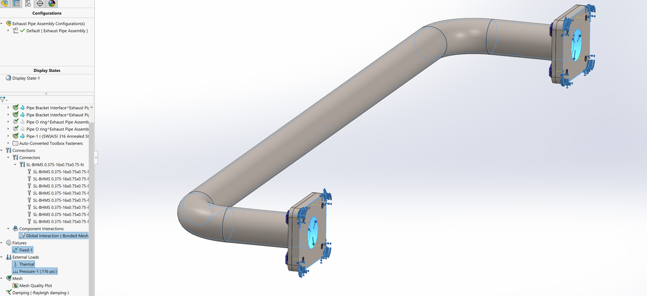
Boundary conditions setup for nonlinear dynamic analysis on the exhaust pipe assembly, showcasing meticulous design considerations and a timed pressure curve ramping up to 116 psi.
Transitioning into the mechanical analysis, a meticulous setup of boundary conditions was essential to ensure the simulation accurately reflects the real-world operational conditions of the exhaust pipe assembly.
The step commenced with the application of bolted connections, generated from smart fasteners, to mimic the actual connections in the assembly. This replaced the previously excluded fasteners with bolted connections, ensuring a more accurate representation of the assembly's mechanical behavior. The O-rings were excluded from this setup, focusing solely on the primary structural components.
A fixed geometry fixture was applied to the two rear bracket edge loops to simulate the constraints the assembly would experience in its operational environment. This fixture helped in realistically restricting the movement of the assembly, providing a more accurate simulation of the mechanical stresses.
To simulate the high-pressure airflow within the exhaust pipe, a pressure load was created. This load was configured to linearly ramp up to 116 psi within the first 2 seconds and maintain that pressure until the 20-second mark. This setup aimed to mimic the pressure conditions the exhaust pipe assembly would encounter during its operation.
Additionally, a thermal load boundary condition was automatically applied from the imported transient temperature results. This integration of thermal and mechanical boundary conditions is critical for analyzing the combined effects of thermal and mechanical loads on the assembly.
The image displaying the boundary conditions provides a clear visualization of the setup, detailing the various conditions applied to the assembly. The depiction includes the distinct boundary condition labeled 'Thermal,' suggesting a temperature-related condition, and 'Pressure-1,' indicating a timed pressure curve. The careful configuration of these boundary conditions is fundamental in ensuring the simulation accurately mimics the real-world operational conditions, laying a solid groundwork for the subsequent analysis steps.
Meshing the Model
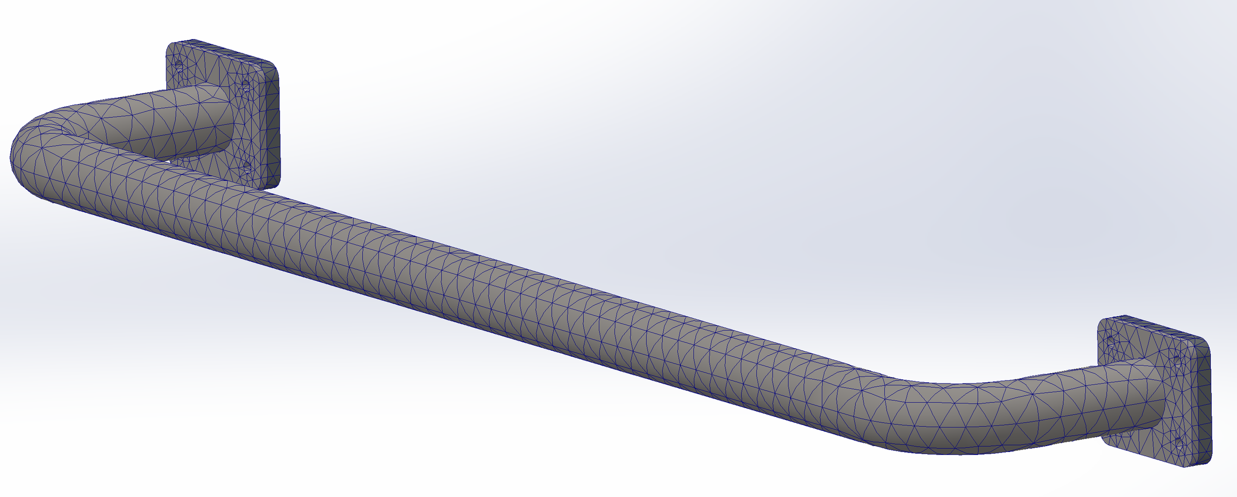
Detailed mesh visualization of the exhaust assembly prepared for finite element analysis, a pivotal step for ensuring accurate results in the subsequent mechanical analysis.
In the preparation phase for simulation, a coarse blended curvature-based mesh was employed to the exhaust pipe assembly, as demonstrated in the image. This meshing strategy was chosen for its ability to adeptly handle the geometric intricacies of the assembly while optimizing the simulation run time. Curvature-based meshing tailors the element sizes based on the curvature of the geometry, offering a refined mesh in areas with high curvature and a coarser mesh in flatter regions. This balance ensures a precise capture of thermal and mechanical behaviors across the assembly without excessively burdening computational resources.
The decision for a coarse mesh was strategic to reduce the solve time while maintaining essential accuracy. Despite its coarseness, the mesh was meticulously calibrated to ensure that critical details were accurately captured, especially in regions anticipated to experience higher gradients of thermal and mechanical stresses. This meshing approach laid a robust foundation for the ensuing analysis, striking a pragmatic balance between computational efficiency and result accuracy, thereby paving the way for a comprehensive exploration of thermal and mechanical stresses within the exhaust pipe assembly.
Running the Study
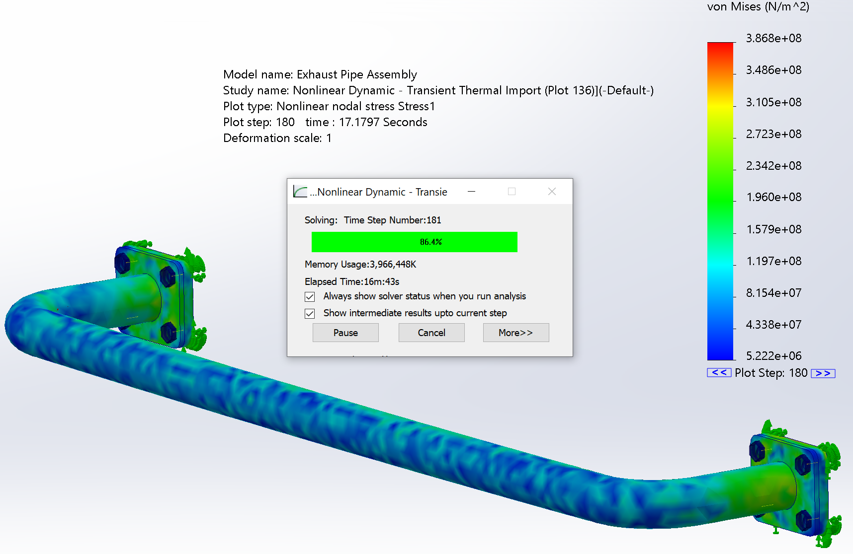
The simulation process was then initiated to delve into the intricacies of the stress distribution within the exhaust pipe assembly. The image showcasing the simulation view provides a glimpse into this critical phase, where the behavior of the assembly under specific thermal and mechanical conditions begins to unfold. The displayed study, labeled as "Nonlinear Dynamic - Transient Thermal Import," specifically at plot 136, pivots around the nonlinear nodal stress (Stress1) with a plot step of 180, corresponding to a time of 17.1797 seconds. The simulation is color-coded to a sidebar scale representing von Mises stress values, offering a clear visualization of stress distributions across the assembly.
The overlaid window titled "Nonlinear Dynamic - Transient" highlights the ongoing progress of the analysis. This window offers real-time insights into the time step, memory usage, elapsed time, and a progress bar, furnishing a transparent view of the simulation's progression. Moreover, it provides options like pausing the analysis and showing intermediate results, granting the analyst control and insight into the unfolding analysis. This phase is fundamental as it transmutes the theoretical setup into actionable data, revealing how the exhaust assembly reacts under the applied conditions, and sets the premise for the ensuing in-depth analysis and interpretation of results.
SolidWorks Simulation view of the 'Exhaust Pipe Assembly' under 'Nonlinear Dynamic - Transient Thermal Import' analysis, providing a comprehensive view of stress distributions and real-time analysis progress.
Analyzing the Results
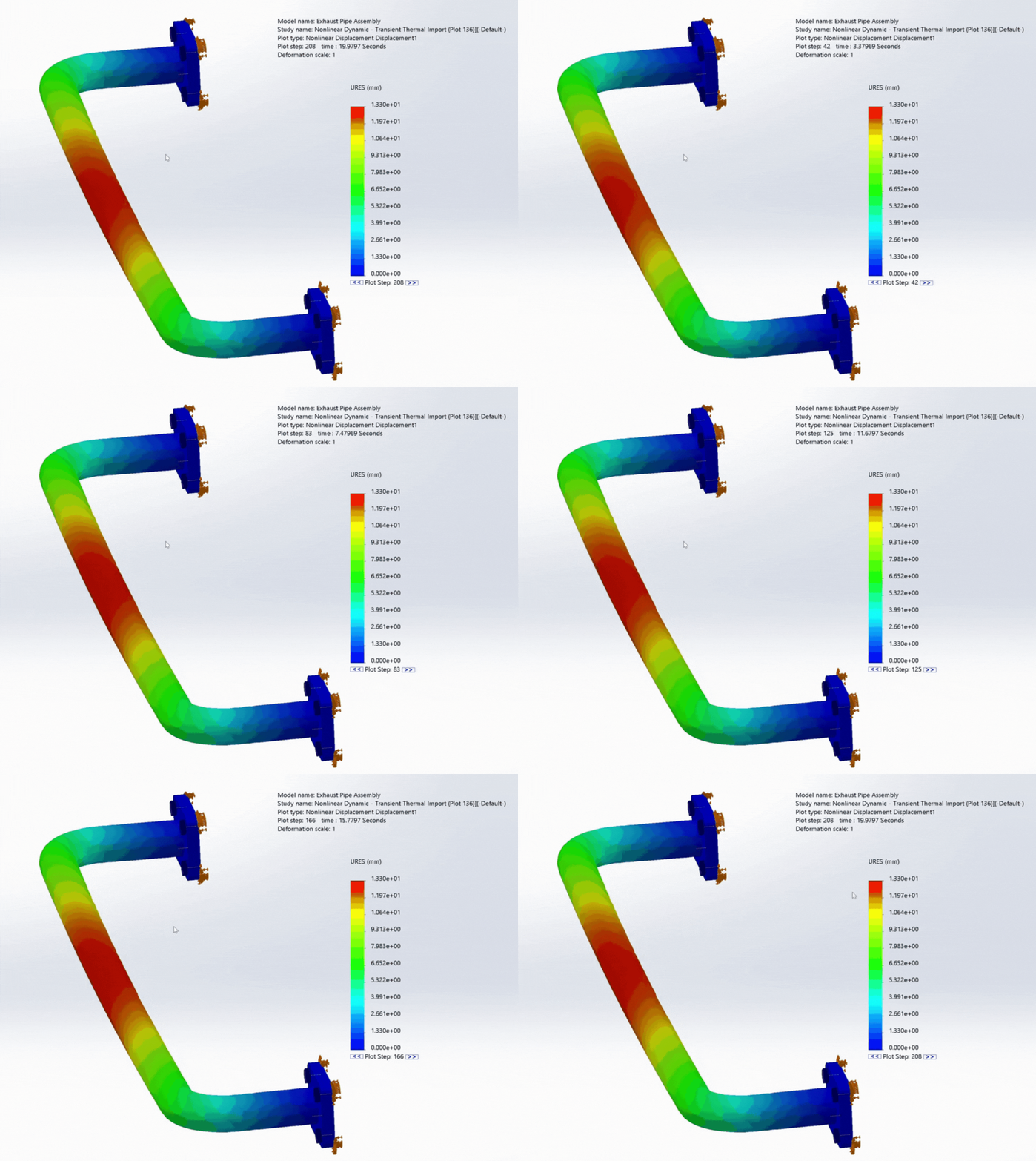
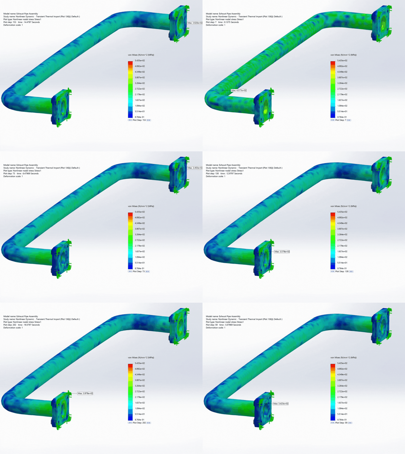
The analysis phase unveiled a wealth of valuable data, serving as a window into the mechanical behavior of the exhaust assembly under the imposed thermal and mechanical conditions. Animated visualizations, as seen in the images, offered a dynamic perspective on the displacement and von Mises stress distribution across the assembly over the span of 0-20 seconds. These animations painted a vivid picture of the structural response, showcasing areas of high stress and significant displacement, particularly around the pipe's flanged ends and the bend region.
The subsequent images present a more nuanced exploration of stress variations over time at specific nodes, accompanied by a detailed response graph. This graph, plotting von Mises stress against time, revealed the stress trajectory at four distinct nodes on the exhaust assembly. Each curve on the graph corresponded to a specific node, illustrating how the stress levels evolved over the simulation duration. The visual juxtaposition of stress distribution on the assembly alongside the response graph provided a holistic understanding of the stress dynamics at play. This comprehensive visualization facilitated a deeper appreciation of the stress hotspots and the overall mechanical integrity of the exhaust assembly under the simulated operational conditions. This data, pivotal for engineering decision-making, underscores the critical interplay between thermal and mechanical factors in influencing the structural performance of heavy machinery exhaust systems.
Animated visualization of the exhaust pipe assembly's resultant displacement during a combined thermal-mechanical nonlinear dynamic thermal transient analysis, depicting the range of displacements in millimeters.
Animated visualization of von Mises stress distribution across an exhaust pipe assembly over a duration of 0-20 seconds, illustrating the areas of stress concentration and relaxation.
Comprehensive visualization of von Mises stress distribution alongside a detailed response graph, offering a profound understanding of stress variations over time for four probed nodes.
Conclusion
The insights gained from this study highlight the complex interaction between thermal and mechanical stresses within a heavy machinery exhaust pipe assembly. This thorough analysis not only emphasizes the importance of careful engineering and simulation but also provides a new level of understanding in exhaust system dynamics. At CADify, we continue to delve into detailed analyses like these, offering our clients a deep level of understanding and expertise that is central to our services in finite element analysis.
As we wrap up this exploration, we welcome you to dive deeper into the world of engineering excellence offered at CADify. Whether you're looking for a consultation or have a full-scale project in mind, our team of experienced engineers is here to assist. We invite you to reach out to us through our contact form or give us a call to discuss how we can help drive your projects to success with precise engineering and expertise. Your next step towards engineering success is just a conversation away, and we look forward to assisting you on your project journey.
About CADify
CADify LLC was founded to provide customer-centric design services to our clients. We take pride in the services we offer and aim for developing a synergistic relationship with our clients. We strive to build long lasting relationships with individuals and companies alike.

