
Optimizing Mechanical Design: A Showcase of CADify's Engineering Expertise
At CADify, we take great pride in our expertise to optimize mechanical designs by harnessing advanced techniques such as Finite Element Analysis (FEA) and design studies. In this blog, we offer a comprehensive, step-by-step demonstration of how our skilled engineers tackled the optimization of an arm bracket design using Solidworks. You'll gain insights into our meticulous approach, which includes creating a 3D model, running simulations, and conducting design studies to fine-tune the design.
Explore how our engineering expertise can assist you in achieving improved designs that boast enhanced performance, cost-effectiveness, and structural integrity. Through our commitment to excellence and attention to detail, we consistently deliver optimized solutions tailored to your unique requirements. Trust CADify to elevate your project with cutting-edge engineering solutions that stand the test of time.
Arm Bracket Optimization

Section 1: Solidworks Modeling - Global Variables, Equations, and Geometry
We begin our optimization process by creating a 3D model of the arm bracket in Solidworks. We use global variables and equations to establish key relationships between dimensions, which allows us to quickly update and adjust the design parameters. By defining the geometry and incorporating parametric design techniques, our team ensures that the model is highly adaptable to future changes.
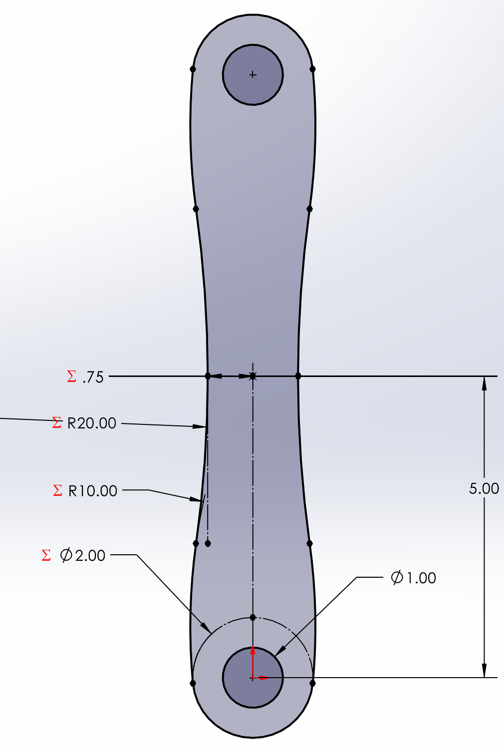
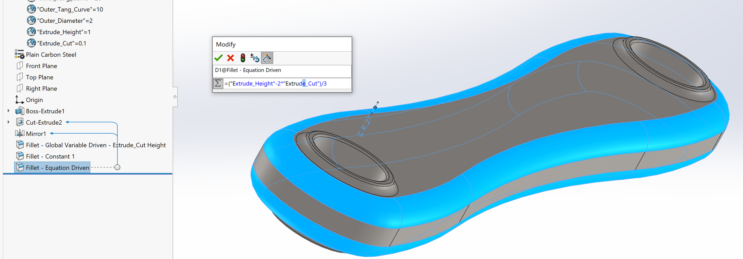
Our engineers create a 2D sketch of the arm bracket, complete with dimensions, and then use the extrude feature to transform it into a 3D model. We further refine the model by adding hole extrude features near bolt hole cut locations and applying equation-driven dimensions. To improve the overall aesthetics and structural integrity, we also add fillets to the hole edges and the perimeter of the arm bracket using global-driven fillet features.
One of the key reasons for linking sketch dimensions and feature dimensions to global variables is to ensure consistency and maintain control over critical design parameters. By doing this, our engineers can easily modify these variables as needed, without having to manually update each individual dimension. This streamlined approach not only saves time but also reduces the likelihood of errors and ensures that design changes propagate accurately throughout the model.
Additionally, establishing global variables at the model level in advance is essential for carrying out design studies effectively. By linking these variables, we create a foundation that allows us to systematically explore and optimize various design parameters within the design study. This helps us identify the most efficient and high-performing design solutions for our clients, ensuring that their engineering requirements are met with precision and expertise.


Section 2: Finite Element Model - Study Properties & Boundary Conditions (Loads & Fixtures)
In this stage, we set up the Finite Element Model by defining study properties and applying boundary conditions such as loads and fixtures. This step is crucial to accurately simulate the real-world behavior of the arm bracket under various forces and constraints.
We enable the Solidworks Simulation add-in and create a new study tailored to the specific requirements of the project. In this case, our engineers select the general simulation type as Static, which is one of several options available depending on factors such as the nature of the loading conditions, the material properties, and the desired level of accuracy.
For the arm bracket, our engineers apply advanced fixtures on the holes, defining radial, circumferential, and axial translation inputs to simulate real-world constraints. It is important to note that the complexity of the fixtures can vary greatly depending on the actual field boundary conditions, making it crucial to select the appropriate constraints for accurate simulation results.
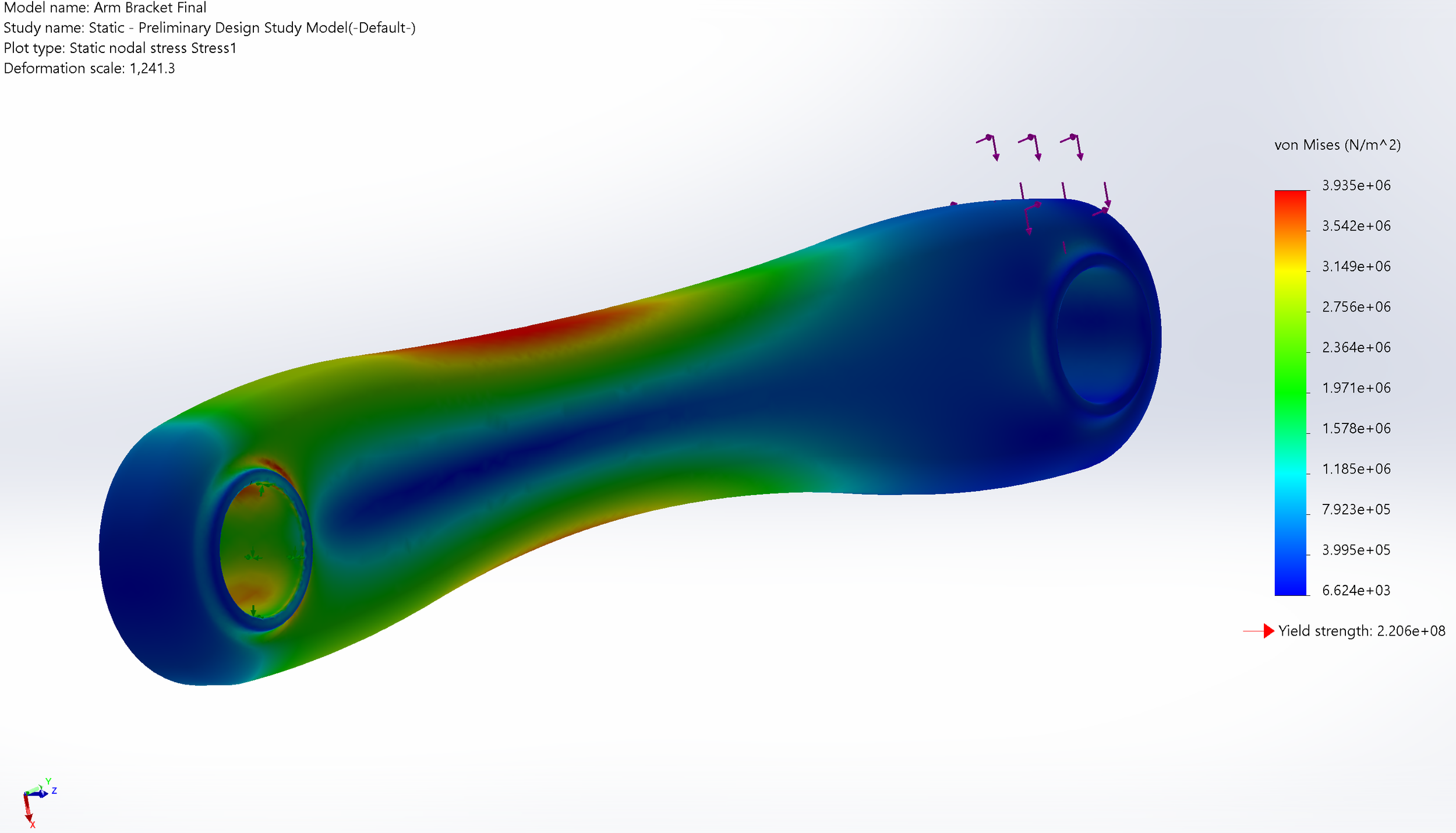
We also apply a loading condition of 25 lb force along two planes, creating forces in the x and y axes. This is just an example of the types of loading that can be applied, and the actual loading conditions may differ based on the specific application and requirements of the project. By applying realistic loads and constraints to the model, we ensure that the simulation results provide valuable insights to help optimize the design and improve its overall performance.


Section 3: Finite Element Model - Meshing, Running, and Results
Once the study properties and boundary conditions are set, we proceed to mesh the model, run the simulation, and analyze the results. This step helps us identify areas of the design that can be improved or optimized for better performance.
Our team creates a mesh using medium mesh density, curvature-based mesh selection, and Jacobian points set to "at nodes." The Jacobian meshing method is employed to evaluate the quality of the mesh elements in the finite element analysis (FEA). By setting Jacobian points to "at nodes," Solidworks assesses the quality of the mesh elements at their corner nodes, helping to identify poorly shaped or distorted elements that may negatively impact the accuracy of the simulation results. Addressing these issues before running the simulation ensures a higher-quality mesh and more reliable outcomes.
The selection of mesh density, curvature-based meshing, and Jacobian settings depends on the specific requirements of the project. Our engineers carefully consider the balance between computational resources and the desired level of accuracy to make informed decisions about these inputs.
After meshing the arm bracket, we run the Solidworks Simulation to generate the von Mises stress fringe plot and the resultant factor of safety fringe plot. These plots help us visualize stress distribution and safety factors, providing valuable insights into the structural integrity of the design.


Section 4: FEA Design Study - Linking and Establishing Variables
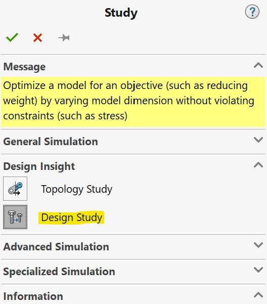
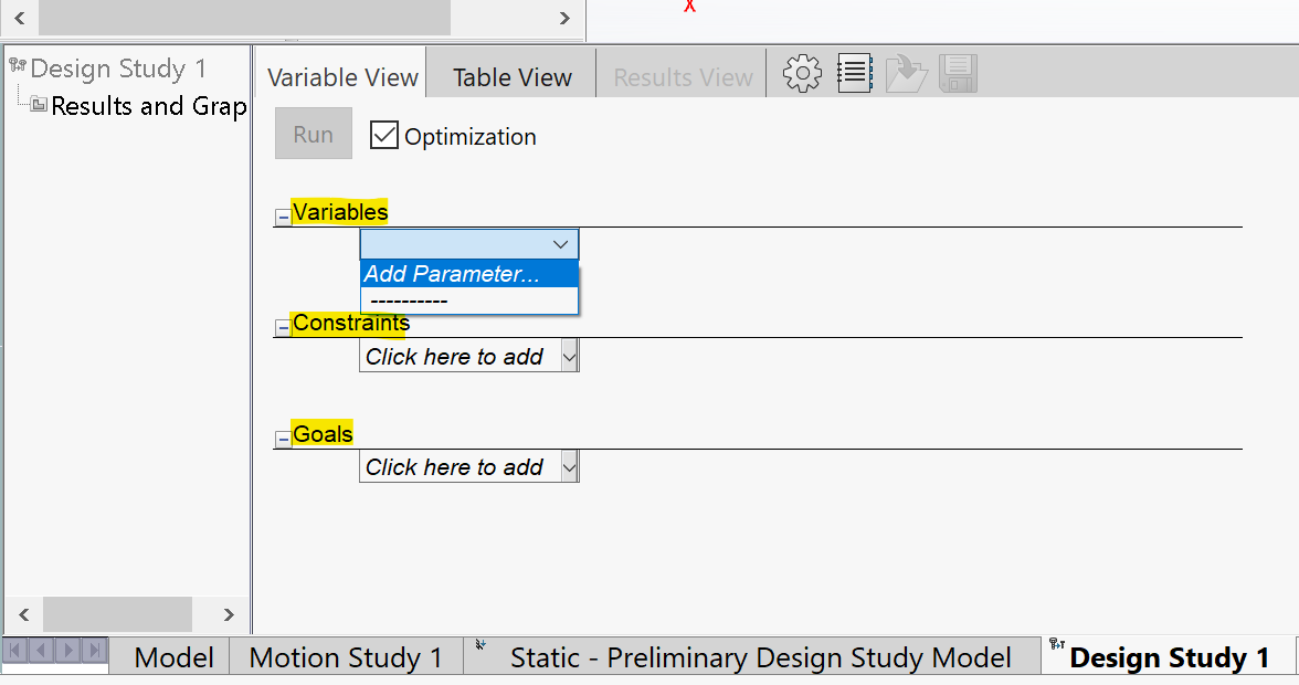
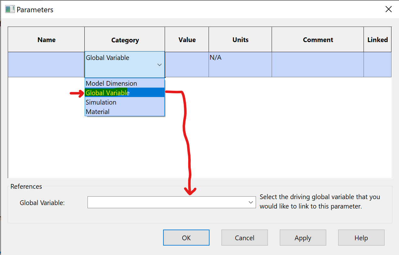
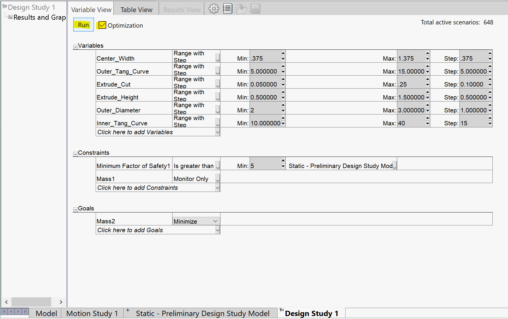
To optimize the design further, we set up a design study in Solidworks that links to the global variables established in the modeling stage. By examining the images we provided, you can see how the design study is set up with various parameters linked to the global variables. This linking allows us to quickly evaluate different design scenarios and identify the most efficient and effective solution by adjusting the global variables, which in turn alter the model's geometry and features.
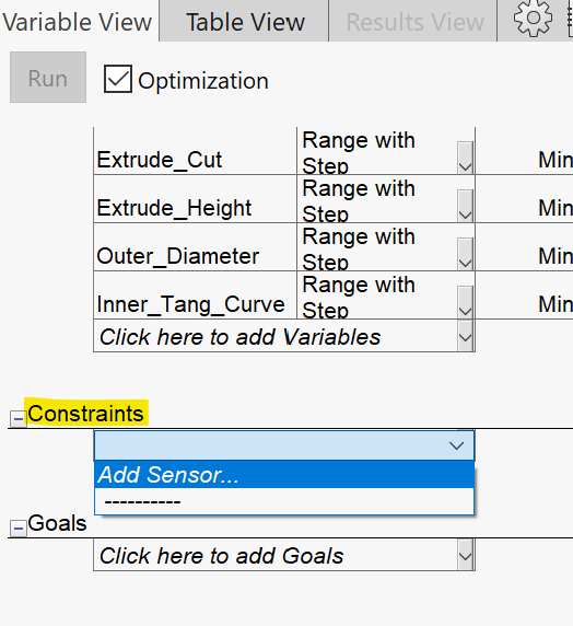
In our design study, we add parameters using the "global variable" option to ensure the model's dimensions and features are controlled by the global variables. Once the parameters are added, we set the variables to "Range with Step" to explore a range of possible design scenarios. As shown in the images, the range and step quantity of each variable are adjusted to reduce the total active scenarios, streamlining the optimization process and saving time during the simulation.
By carefully examining the range of possible design scenarios, CADify's engineering team can identify and recommend the optimal solution, ultimately leading to a more efficient, robust, and cost-effective design for our clients.


Section 5: FEA Design Study - Constraints, Sensors, and Goals
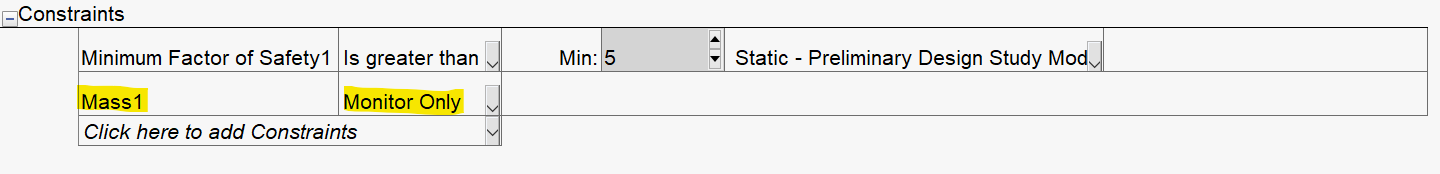
In relation to our images, we define constraints, sensors, and goals for the design study to guide the optimization process and ensure the optimized design meets specific performance and safety requirements while minimizing weight and material usage.
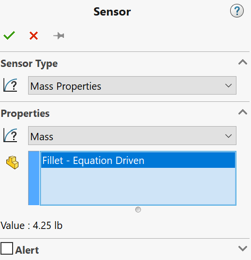
Our images show the process of adding sensors for simulation data, such as the factor of safety, and mass properties to monitor the mass of the arm bracket. These sensors allow us to track critical design parameters throughout the optimization process. Constraints are established to ensure that the minimum factor of safety is greater than a specified value (as demonstrated in the images), and the mass of the arm bracket is monitored to keep it within acceptable limits.
Once the constraints and sensors are in place, we set the goal of the design study to minimize the mass of the arm bracket while maintaining the required performance and safety levels. This is illustrated in the images, where the goal is linked to the mass sensor, and the optimization is set to minimize the mass.
As the design study runs through various scenarios, it evaluates each one based on the defined constraints, sensors, and goals. The images showcase the progress of the design study, with the optimized arm bracket model being displayed along with the most optimal scenario identified. The results also show the new global variable values for each scenario, providing valuable insights into the most effective design changes.
Through this comprehensive optimization process, CADify ensures that the final design is not only lightweight and efficient but also meets the performance and safety requirements essential for our clients' projects.


Section 6: FEA Design Study - Running, Results, and Insight
As illustrated in our images, CADify's engineering team runs the design study to identify the most optimal design solution, showcasing our ability to efficiently and effectively optimize mechanical designs to meet specific requirements.
We execute the design study, which evaluates multiple scenarios, taking into account the variables, constraints, and goals that we previously defined. The images display the progress of the design study, with the optimized arm bracket model being shown alongside the most optimal scenario identified. The results provide valuable insights into the improved global variable values and the optimized factor of safety and mass values.
Armed with this information, our engineers can refine the arm bracket design to strike a balance between performance, safety, and cost-effectiveness. The images demonstrate the results of the optimization process, highlighting the significant improvements made in terms of the factor of safety, which increased from an initial value of 53 to an optimized value of 14, and mass reduction, where the mass was reduced from an initial 4.25 lb to an optimized value of 1.11 lb, without compromising the design's integrity.
By employing such a thorough optimization process, CADify ensures that the final design not only meets our clients' requirements but also achieves a balance between performance, safety, and cost-effectiveness, setting us apart from the competition. Our expertise in design optimization translates into tangible benefits for our clients, ensuring their projects are completed efficiently, with enhanced structural performance and cost savings.


Partner with CADify for Product Design Optimization
CADify's expertise in mechanical design optimization using advanced techniques like FEA and design studies ensures that our clients receive the highest quality engineering solutions. Our commitment to efficiency, performance, and cost-effectiveness is evident in this arm bracket optimization example. If you're interested in harnessing the power of our engineering expertise for your next project, schedule a free 30-minute consultation or fill out our contact form today.
About CADify
CADify LLC was founded to provide customer-centric design services to our clients. We take pride in the services we offer and aim for developing a synergistic relationship with our clients. We strive to build long lasting relationships with individuals and companies alike.